
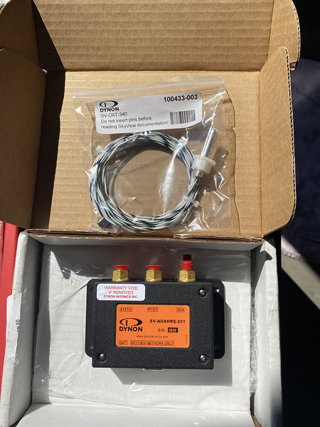
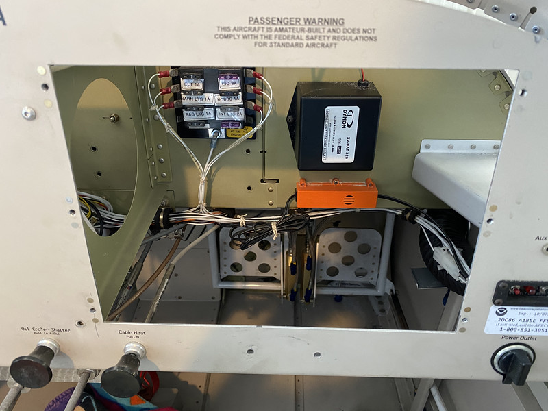
My quest to eventually equip the RV-9A for Instrument Flight Rules (IFR) flying has gotten underway. I started by adding a secondary Attitude Data and Heading Reference (ADAHRS) unit. The ADAHRS is the brain for the EFIS screen’s flight data. It has an Outside Air Temperature (OAT) probe, and an attitude and magnetic heading reference, along with the Pitot/Static/AOA air data references. Having dual ADAHRS gives you redundancy so if you are in IFR, and they disagree to some parameter, you can swap over to the backup.
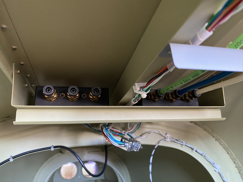
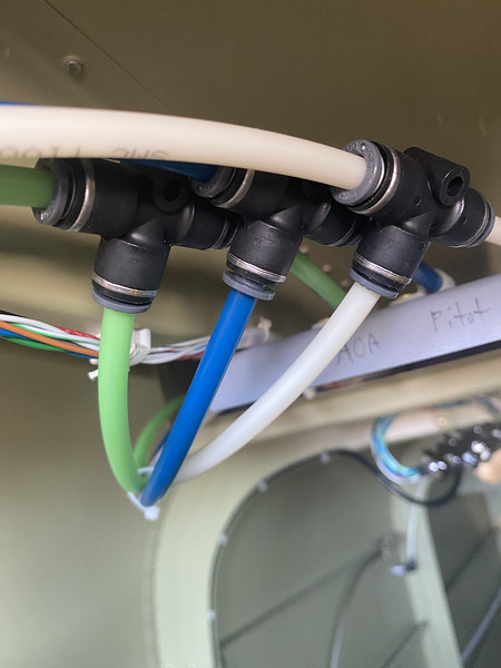
The secondary ADAHRS unit was new, but unused, and I got a pretty good deal on it from another builder. I already had the necessary pitot/static/AOA tubing adapters and tees to add it into the airplane. The ADAHRS shelf that I fabricated in the airplane was designed for another unit to be set next to the primary ADAHRS unit. I just needed to bolt it in place (with brass hardware that is non-magnetic), insert the tees for the tubing and connect them up. The new unit also has its own OAT probe that needed to be installed back in the fuselage and wires run up to the unit. This was the hardest part of the installation. I had to just wedge myself back in to the aft fuselage to secure the new wires to the others that are run along the fuselage. I already had a Dynon Skyview network cable splitter connector to use to connect both ADAHRS units to the network.
After powering up the unit, I had to do some compass calibrations on the ground and in the air, then some stalls to set the AOA. The elevation calibration also had to be set so both units were seeing the same altitudes.
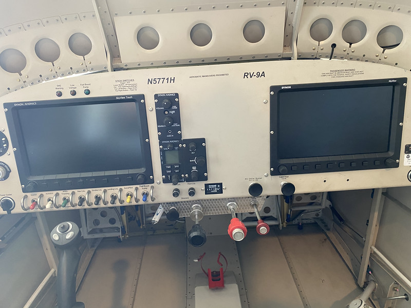
The next upgrade was to add a second EFIS display. I had originally laid out the panel to have room for a second 10″ display. After flying this single display panel for the last 6 years, the display started to misbehave. I’m not sure what caused this, but on several occasions the screen would be unreadable (just lots of colorful pink/blue lines). Usually, a power up and reboot or two would get it operating normally. The issues finally became too frequent, and then it just permanently failed. Thankfully, I was at my home airport and was only planning on flying around the pattern when it finally gave up for good. After pulling out the screen, and sending it back to be repaired (twice!), it was ultimately replaced with a newly remanufactured unit by Dynon. I was now ready to get some true redundancy since all of the required flight instruments are on the EFIS display, and with only one screen, you are grounded if that single display is not working. If you had this single screen fail away from home, you would be screwed until you could get the display repaired.
I started looking in the VAF classifieds for any deals on a used Dynon Skyview Classic or Touch version of the display. I would have liked to just gone ahead with an upgrade to the new Skyview HDX, but that would have cost me a whole lot more money than I wanted to spend. The HDX is nice, but it doesn’t really have any additional features beyond what the Classic display provides. I ended up getting a good deal on a lightly used Skyview Touch display (less than 400 hours on it). This screen is compatible with the Classic screen (non-touch) that I have. I also was able to buy an new and unused Dynon EFIS harness to connect this new screen to my existing screen. There are a couple of other items that are needed for the upgrade, and I purchased those from Aircraft Spruce – an ethernet network cable, wifi adapter dongle, and an EFIS backup battery. All of this was less expensive than just buying a single new Classic screen!
I got to work on the panel by removing the existing units. I measured out the location for the new EFIS and started drilling holes in the corners of the rectangle shaped area. Then using the cutting wheel, I connected the dots to get a rough sized opening. A whole lot of filing down the edges was needed to get it to the right size, and I was finally able to slide the unit in place. Then I marked the mounting holes, drilled them and installed the nutplates for the mounting screws on the display.
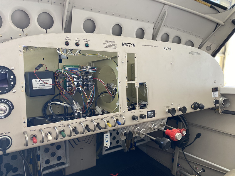
I reinstalled the various units and reconnected everything. I took out the new Dynon EFIS harness and made sure that it would reach across to my 25-pin D-sub hub. The unterminated wires on the EFIS harness are all uniquely color-coded and are easily identified. Some of the wires do not get connected to the other display, such as the DIMMER OUTPUT, AP LEVEL and GO AROUND contacts. There are dual power and ground wires that get connected to the Vertical Power VP-X power unit and the central ground block tabs.
Dynon also requires that you install an ethernet cable between the two displays. I got the new EFIS harness terminated in to the 25-pin D-sub connector hub that is also plugged into the primary screen. I had to fabricate a new Skyview Network cable to connect both screens (in addition to the ethernet cable). I spent a bit of time under the panel (not the most fun place to be) getting the power and ground wires connected up. The new 5 amp power wire required for the display meant that I had to insert a new VP-X power wire into its connector for this circuit. I had put aside the remaining unused VP-X power wires back when I was building the airplane, and I was able to find them in my boxes of wiring supplies. The wires have a special type of connector already crimped on for the VP-X power connectors. I had to disconnect and unmount the VP-X box under the panel just to be able to reach the ground block for the dual ground wires. There was not much room way up there for my hands to reach it with the box mounted in its place. Lastly, there are a pair of wires that go to the backup battery, and a USB port on a short cable that I attached under the panel.
Once I had the electrical connections all set, I powered up the VP-X so that I could run the VP-X configuration program to enable the new power wire as part of the Avionics switch. The single Avionics switch on the panel powers up and turns on several other circuits on the VP-X power unit. You have to plug in a special crossover ethernet cable from your laptop to the VP-X box to do this. Once the new configuration was in place, I was able to switch on both displays from the panel switch.
I found that I needed to re-run the entire network configuration setup to get the new screen recognized, and for it to recognize all of the other Dynon network devices. I was able to then tell the original screen to export all of the airplane configuration and map data over to the new primary Touch screen display. I kept getting a GPS LOCATION failure, so I had to dig around in the setup menus. I found that they both needed to be told that I had the SV-GPS-2020 antenna, instead of the default SV-GPS-250. The EMS config files were loaded back in from my USB thumb drive to each screen, so they were more or less in synch. I still had some tweaking to do in the SETUP MENU for the Dual screens. Some of the options are only available if you have more than one screen. There is a reversionary mode that you can configure so that if one of the screens fails, or power is turned off, the other one knows what to display as a backup. There are also some unique settings for the Touch screen that needed to be selected.
The new screen also insisted that I perform the COMPASS and AOA calibration routines. I took the airplane over to the compass rose at the airport and did the simple ground calibration by setting a rough N/S/E/W direction. After that, I took off and flew the in-air compass calibration routine, which is just flying a circle to the left and a circle to the right. The AOA calibration required a couple of stalls for calibration. The backup battery test also needed to be done. The new battery wasn’t fully charged, and I was unable to do the 45 minute test on that battery. The old battery was able to pass the test, so I will just need to fly longer to recharge the batteries and re-run the test.
Having the second screen gets me a little closer to IFR capable, but I will still need to buy and install a Garmin certified GPS navigator. I have enough room on the existing panel for the GPS 175, but it will require me to move around the existing Intercom, COMM radio and Knob Panel units that are in the center of the panel to new locations. The Garmin GPS unit speaks a different “language” so I will have to get the SV-ARINC-429 box from Dynon installed to do the translations. Lastly, a heated Pitot/AOA probe will be needed to handle any icing caused by flying in the clouds or in moisture. Once I get these added to the airplane, then I will buckle down and start the IFR flight training. I completed the Instrument ground instruction this year at Miramar College, but I haven’t taken the FAA written yet.
